'Broad Gauge Era' Signalling Equipment
Introduction
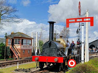
At the northern end of Didcot Railway Centre in the area controlled by Frome Mineral Junction Signal Cabin the Great Western Society has assembled a unique presentation of artefacts of the broad gauge era.
The 'star attraction' of this display is of course the replica broad gauge locomotive 'Fire Fly', but perhaps equally important historically are the Transfer Shed and the broad gauge trackwork itself.
In introducing signalling equipment to this area, we have been careful to ensure that all the items are 'period'. This has included everything from the signal cabin itself, and of course the signals, through to the humble wire and rodding runs and the telegraph posts and wires.
In trying to re-create the 1870's, where much of the equipment has not been manufactured for well over one hundred years, more use has inevitably been made of replica castings, timberwork, and other materials, than has been the case in other areas of the signalling display. We are most grateful to the PRISM fund of the Science Museum for their financial assistance with this part of the project.
Detailed historical information on how the Brunel's broad gauge railway was signalled is extremely sparse and much reliance has been placed in spotting equipment in the background of photographs intended to display Broad Gauge trains, and in the use of general engineering principles to ascertain how certain items must have been made in order to function.
A useful document has been the Great Western Railway's 'Standard Signal Fittings' stores catalogue of 1908, which often not only illustrates the complete item, but also the separate components which go into its makeup.
Point Rodding
Rodding and Rollers
The roller boxes are replicas based on illustrations contained within section S - 'Sundry Point Fittings' of the catalogue of the GWR signalling stores at Reading, dated 1908. The three piece construction, described as '2. Roller Box Casting, 3. Roller Box Cover and 4. Roller Box Wheel', all go to make '1. Roller Box'. For comparison the more usual open rodding roller casting is described as a '6. Travelling Roller'.
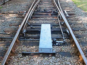
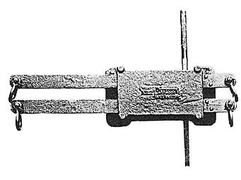
Compensators
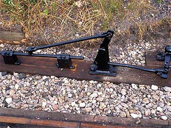
Compensators are used to reverse the direction of travel of the rodding run, in order to compensate for the effects of thermal expansion. The 'modern' compensator involves two angle cranks, joined by a short rod. Some very early pictures shew this requirement being met by a vertically mounted centre pivoted arm, and it is this that we have reproduced at Didcot.
All three of these compensators are pictured here. The single one (left) is on the run to the scotch blocks and the pair (right) are the point and facing point lock rods for the pointwork on the mixed gauge side of the transfer shed.
For a picture of such a Compensator in use in 1890 at Newton (Abbot) see Karou, 1985, p. 28
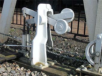
FPL on Mixed Gauge Point
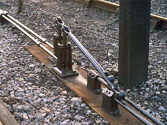
The Facing Point Lock on the mixed gauge point is most unusually mounted outside the line of the rails. The apparatus itself is a replica based on illustrations contained within section P - 'Parallel Bar Bracket Fittings' of the catalogue of the GWR signalling stores at Reading, dated 1908. The main casting is described as '43. Box Casting', the plunger as '56. Plunger complete, ordinary' and the blade as '57. Blade'.
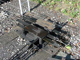
FPL on Standard Gauge Point
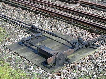
The point giving access to the two transfer shed platforms is located just south of Frome Box. Whilst the locking mechanism on this point is conventional, discounting the double locking bar arrangement, the FPL cover is of an older pattern. In this type, the cover rather than being hinged on one side, is instead slid aside on two round-bar 'runners'.
The components of this FPL cover are illustrated within section P - 'Parallel Bar Bracket Fittings' of the catalogue of the GWR signalling stores at Reading, dated 1908. The replica FPL cover is listed in the catalogue as '58. Plunger Cover Plate' together with '59. Plunger Cover Plate Rod, 60. Plunger Cover Plate Bearing, Left Hand' and '61. Plunger Cover Plate Bearing, Right Hand'.
For a picture of such an FPL cover in use in 1925 at Colnbrook see Russell, 1979, pl. 292
Signal Wires
It might be supposed that signal wires have remained pretty much unchanged over the years, but this is certainly not true of their method of support. The signal wires and associated equipment connected to Frome Mineral Junction Cabin, display many peculiarities, long since wiped from the national railway scene.
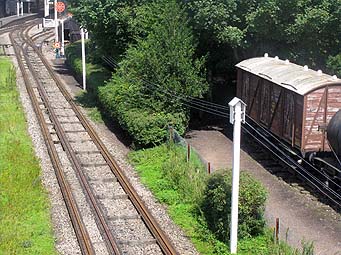
Overhead Wires
R J Heron 10-May-2003
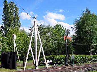
It was noted that some photographs showing broad gauge scenes had strangely placed angled white posts, and further research showed that these were supports used to carry the signal wires overhead. Photographs showed such installations at Swindon, Newton Abbot, Taunton and Lydney Junction.
There is very little recorded information on this subject, the only reference in a modern signalling work that has been found is in a caption to an 1882 picture of the Gloucester Wagon Company built box at Wakefield on the L&Y. This states that “The large timber framework at the left carries the signal wires above the lines, as was done at some complicated locations at this period instead of taking them beneath the rails”.
(Signalling Study Group 1986. p.100)
Questions on overhead signal wires that it would be good to answer include; who carried out this work, when, and why ?
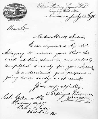
It is perhaps significant that early signalling work, prior to 1876, at Swindon, Newton Abbot and Taunton, where examples of overhead signal wires are to be found, was all carried out by the contractors, Saxby and Farmer. Indeed one picture clearly shows an overhead support post adjacent to a Saxby & Farmer 'Type 4' box, Newton Abbot's 'middle' box.
(Signalling Study Group. 1986. pp 81-83; Rice. p.40)
S&F were clearly not the only contractors following this practice. As has been noted above, an overhead wire installation at Wakefield was carried out by the Gloucester Wagon Company, and it is possible that this company was also responsible for the installation at Lydney Junction.
The overhead signalling equipment at Didcot is based on pictures of Swindon and Newton and is therefore of a type which appear to have been installed by Saxby and Farmer.
Precisely when this equipment was installed is unclear. It was clearly of the pre-1892 broad gauge era and some of the published photographs are dated to the mid 1880's. The majority of the South Devon Railway was interlocked between 1874-6 though the only available Railway Inspectorate report of this period, relating to work between Newton and Kingskerswell in 1876 (TNA MT6/161/10)makes no mention of overhead signal wires.
(Signalling Study Group. 1986. p.165)
Similarly the initial interlocking work at Swindon was undertaken in 1874, but again the only available Railway Inspectorate reports of this period, relating to work at Swindon in 1872-1875 (TNA MT6/121/18: MT6/141/15) make no mention of overhead signal wires.
(Signalling Study Group. 1986. p.160)
We can only assume therefore that the equipment was installed during the initial interlocking of these areas in the mid 1870's.
These views on Swindon are confirmed by Colin Maggs who has independently concluded that “In about 1874 signal-boxes were brought into use between Paddington and Bristol working a mixture of semaphore and disc-and-crossbar signals. The early semaphore signals at Swindon were made by Saxby and Farmer and their operating wires were carried overhead, instead of at ground level, giving a more direct route.”.
(Maggs. 2003. pp.133-135)
Published Photographs showing Overhead Signal Wire Equipment |
|||
|---|---|---|---|
| Location | Publication | Date (where given) | |
| UNKNOWN | Treloar, P.Q. 1985 | Plate 17 | Loco dates picture as 1849 - 1888 |
| Hereford Barton | Spence, J. 1977 | Plate 119 | 1886 |
| Newton Abbot | Rice, I | p.27 | |
| p.40 | Loco dates picture as 1865 - 1892 | ||
| Karau, P. 1985 | p.25 | July 17th 1889 | |
| Swindon | Peck, A. 1983. Dust Jacket Maggs C.G. 2003. p.151 |
c. 1890 (Maggs) | |
| Peck, A. 1983 | p. 74 | 'About 1887' | |
| Peck, A. 1983. p. 118 & Russell J.H. 1978. pl.152 & Maggs C.G. 2003. p.38 |
October 1st 1895 | ||
| Taunton | Broad Gauge Society | Plate 14 | |
| Lydney Junction | Copeland, L.E. 1983 | p. 6 | |
A further reference to the practice, is made in one of the earlier signalling texts, namely H Raynar Wilson's definitive 'Mechanical Railway Signalling' of around 1911, where he states that “The type of carriers shown ... will be found useful where it is impossible to run the wires on, or under the ground, and they have to be carried overhead. In such cases high posts are provided about 25 yards apart, and a fixed wire run from post to post, and to this wire may be attached carriers such as have been described ...” (TNA ZLIB7/6).
As well as the published and public sources quoted above, I should like to thank: Gordon Roberts of the Signalling Record Society, who has provided assistance with this research.
(Section still being researched)
Ground Level Wires
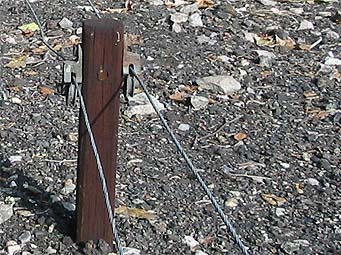
There is nothing particularly surprising about early ground level signal wires, the only distinguishing feature being that the pulleys are mounted on hardwood posts rather than the more familiar, modern, angle iron stakes.
Point/Signal Detectors (Plunge Type)
These detectors are assembled from new castings based on the illustrations contained within section E - 'Detectors' of the catalogue of the GWR signalling stores at Reading, dated 1908.
The replica is of a plunge detector, listed in the catalogue as '5. Detector, Old Pattern, Double'.
The plunge detector is used for signals 1 & 2
Point/Signal Detectors (Slide type)
These detectors are assembled from new castings based on the illustrations contained within section E - 'Detectors' of the catalogue of the GWR signalling stores at Reading, dated 1908.
This replica, of which we have made two, is simply listed as '2. Detector, Double'. It is similar to the more familiar slide detection, but is far more enclosed than its more modern counterpart.
The slide detectors are used for signals 15, 16 and 17.
Other Features
Scotch Blocks
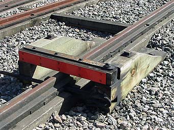
Our Scotch Blocks are based on the drawing produced by the Broad Gauge Society (Reference Sheet 77/2.2).
For a picture of stop blocks in use in 1895-8 at Torquay see Russell, 1978, pl. 85
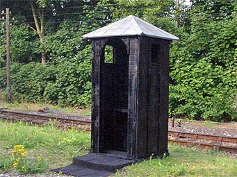
Policeman's Hut
Trains on the Great Western, like other railways of the time, were initially controlled by the Railway Police, using hand signals.
R J Heron 07-Aug-03
The first mention of police boxes is on 24th August 1838, two months after the opening of the line to Maidenhead. On this date estimates for 'Police Boxes' together with 'Lamps for the Police' were requested by the London Committee.
(MacDermot. 1964. p. 309)
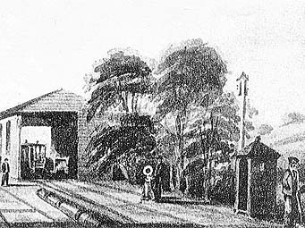
Whilst the hand signals were soon augmented by assorted fixed signals, the policeman's hut remained the only shelter for the man controlling such signals until the advent of the locking boxes in the 1860's and 70's.
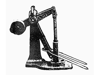
'Capstan' Signal
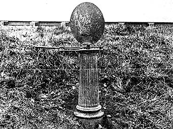
The earliest form of fixed signal on the Great Western was the capstan, designed by Brunel for working points and at the same time indicating their position. It was introduced in 1839 when “Slaughter and Co. of Bristol, supplied many 'sets of switches complete with capstan, disc and quadrant' for £50 each”.
The horizontal lever, working in a quadrant frame, drove an iron spindle and thus the connecting rod at the base which operated the point, and also the large circular target. The target being face on to the traffic indicated that the points were set for the main line.
(MacDermot. 1964. p. 310)
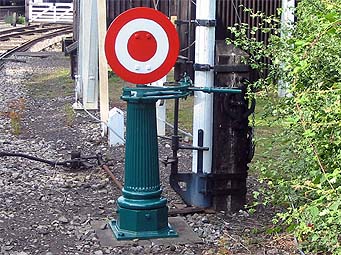
Our Capstan signal is based on the drawing produced by the Broad Gauge Society (Reference Sheet 96/1.1) and shows a later type of capstan as produced by Rowland Brotherhood of Chippenham. Brotherhood had worked for Brunel as a Civil Engineer on the cuttings and embankments of the original GWR London-Bristol line and started a works in Chippenham in 1842 to build and repair earth moving equipment. However he quickly diversified into manufacturing signals and points and later bridges, wagons and even locomotives. This works was later used by Evans O'Donnell, and Saxby and Farmer, later to become the Westinghouse Brake and Signal company.
Telegraph Posts
These are based on those of the South Devon Railway which were installed and maintained by the Electric Telegraph Company (later The Electric and International Telegraph Company). This company was formed in 1846 by Sir William Fothergill Cooke (of Cooke and Wheatstone fame) and Joseph Lewis Ricardo. The maintenance contract was concluded on 31st January 1870 when responsibility for all such telegraphs was handed to the Postmaster General as a result of the Telegraph Act, January 28 1868 (TNA RAIL1057/3009).
Bibliography
Broad Gauge Society, The. Taunton in the 1880's. The Broad Gauge Society. |
| Copeland, L E. Severn & Wye Railway: Volume 1. Wild Swan. ISBN 0 906867. |
Great Western Railway, G.W.R. Stores Department Reading. Standard Signal Fittings. Swindon. January 1908. |
Karau, Paul. 1985. Broad Gauge Finale. Wild Swan. ISBN 0 906867 31 2. |
MacDermot, E.T. 1964. History of the Great Western Railway: Volume One 1833-1863. Ian Allan Ltd. ISBN 0 7110 0411 0. |
Maggs, Colin G. 2003. The GWR Swindon to Bath Line. Sutton Publishing Limited. ISBN 0 7509 3403 4. |
Peck, Alan. 1983. The Great Western at Swindon Works. Oxford Publishing Company. ISBN 0 086093 177 3. |
Rice, Iain, et al. Undated. A Broad Gauge Album. Newton Abbot GWR Museum, 2a St. Paul's Road, Newton Abbot. TQ12 2HP. |
Russell, J.H. 1978. Great Western Miscellany (Volume 1). Oxford Publishing Company. ISBN 0 902888 88 9. |
Russell, J.H. 1979. Great Western Miscellany (Volume 2). Oxford Publishing Company. ISBN 86093 029 7. |
Signalling Study Group, The. 1986. The Signal Box. Oxford Publishing Company. ISBN 0 86093 224 9. |
Spence, J. 1977. Victorian and Edwardian Railway Travel from Old Photographs B T Batsford Ltd, 4 Fitzhardinge Street, London W1H 0AH. ISBN 0 7134 0639 9. |
Treloar, Peter Q.1985. The Earle Marsh Album. The Firefly Project Limited, Market Hill House, Calne, Wiltshire. |
In addition, various copies of the Great Western Echo (GW Echo), Great Western Society National Newsletter (GWS NN) and Great Western Society (Bristol Group) News (BGN), all published by the Great Western Society, have been consulted.
Original Documentation has been consulted at The National Archives at Kew (TNA).